⚡ Electricity & D.C. Circuits (Master Note)
Syllabus: Chapters 9 & 10 (Cambridge International AS Level Physics 9702) Tags: physics electricity circuits A-Level #9702
📑 Table of Contents
- Electric Current & Charge
- Potential Difference, E.M.F., & Power
- Resistance & Resistivity
- I-V Characteristics
- D.C. Circuits & Kirchhoff’s Laws
- Potential Dividers & Potentiometers
- Essential Past Paper MCQs
1. Electric Current & Charge
Official CIE Definitions
Electric Current: The rate of flow of charge carriers. Quantised Charge: Charge only exists in discrete amounts (multiples of the elementary charge, ).
Core Equations
Where is charge in Coulombs (C), is current in Amperes (A), and is time in seconds (s).
Current in a Current-Carrying Conductor
The current can be expressed in terms of the microscopic properties of the conductor:
- : Cross-sectional area ()
- : Number density of charge carriers (number per unit volume, )
- : Average drift speed/velocity ()
- : Charge of the charge carrier (for electrons, )
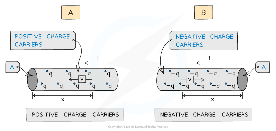
Examiner Tip: Conventional Current vs Electron Flow
By definition, conventional current always goes from positive to negative. In metals, the actual charge carriers are electrons (negative), which flow from negative to positive. They flow in opposite directions, but the math works out the same!
2. Potential Difference, E.M.F., and Power
These two definitions are the most frequently tested 1-2 mark questions in Paper 2. Memorize them exactly as written in the Mark Scheme.
E.M.F. vs P.D. (Mark Scheme Standard: e.g., 9702_m19_qp_22-Q6)
- Electromotive Force (e.m.f.): Energy transferred from chemical/other forms to electrical energy per unit charge (driven around a complete circuit).
- Potential Difference (p.d.): Energy transferred from electrical energy to thermal/other forms per unit charge (across a component).
Equation: (where is work done / energy transferred).
Electrical Power
Power is the rate of doing work. Using , we can substitute to get three variations:
Mnemonic
Think: “Twinkle Twinkle Little Star, Power equals squared “. Use when voltage is constant (e.g., parallel circuits), and when current is constant (e.g., series circuits).
Internal Resistance and Lost Volts
All real power supplies have an internal resistance (). This causes some energy to be dissipated as heat inside the battery before it reaches the external circuit.
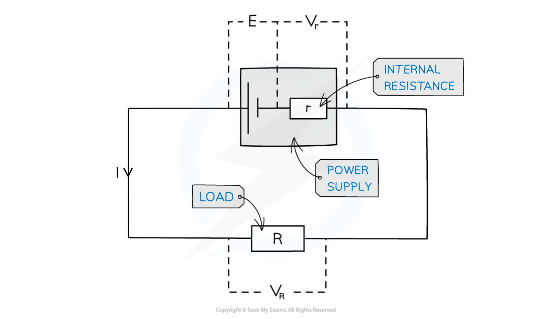
Where: = e.m.f., = terminal p.d. (), and = lost volts.
High-Yield Graphic Analysis (Paper 2 & 3)
If you plot a graph of Terminal p.d. () against Current ():
- y-intercept = e.m.f ()
- gradient = (negative internal resistance)
3. Resistance & Resistivity
Definition of Resistance and the Ohm
Resistance: The ratio of potential difference across a component to the current through it (). The Ohm (): One volt per ampere ().
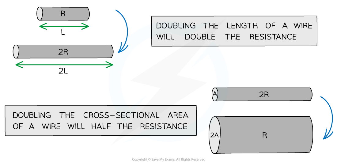
Resistivity ()
Resistivity is a property of the material itself, independent of its shape. Resistance depends on resistivity, length, and cross-sectional area:
Common Exam Trap
Exam questions rarely give you the Area () directly. They give you the diameter (). Remember: . Therefore, if the diameter doubles, the Area increases by a factor of 4, so Resistance drops by a factor of 4!
Sensory Resistors
- LDR (Light Dependent Resistor): As light intensity increases, resistance decreases. (More light frees up more charge carriers).
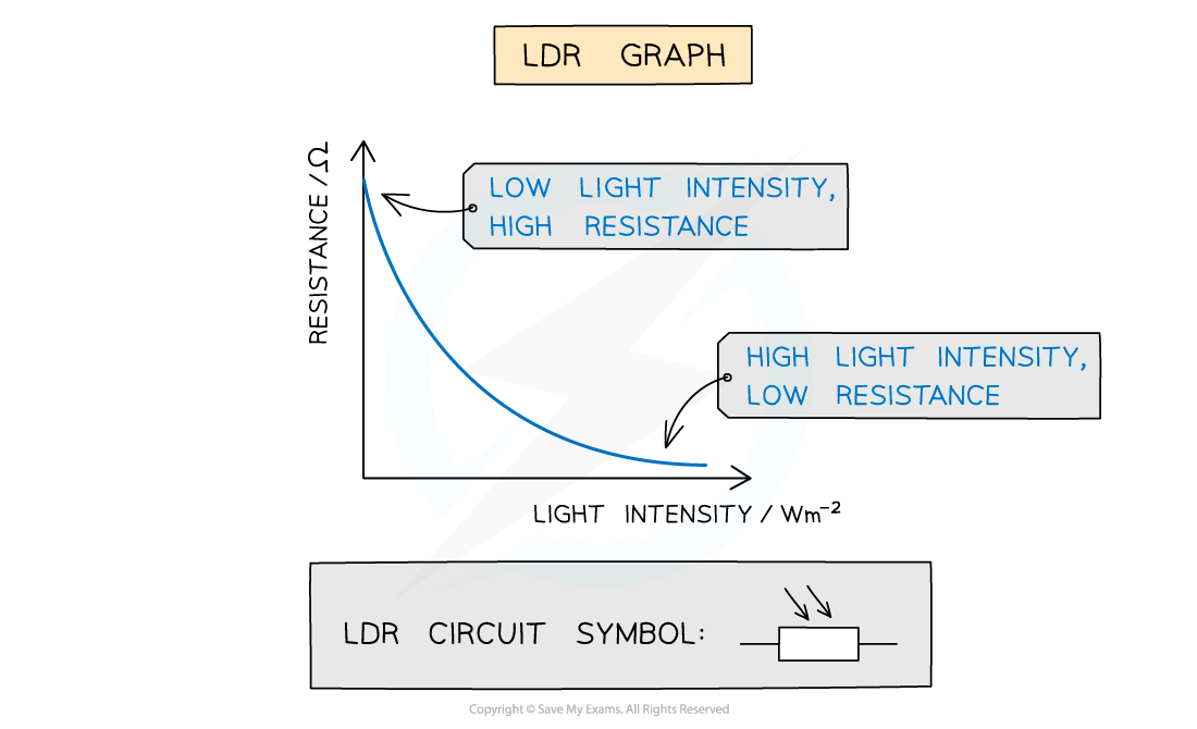
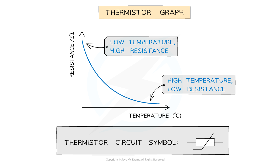
- Thermistor (NTC): As temperature increases, resistance decreases. (Thermal energy frees electrons, drastically increasing number density ).
4. I-V Characteristics
You must be able to sketch and explain these three graphs:
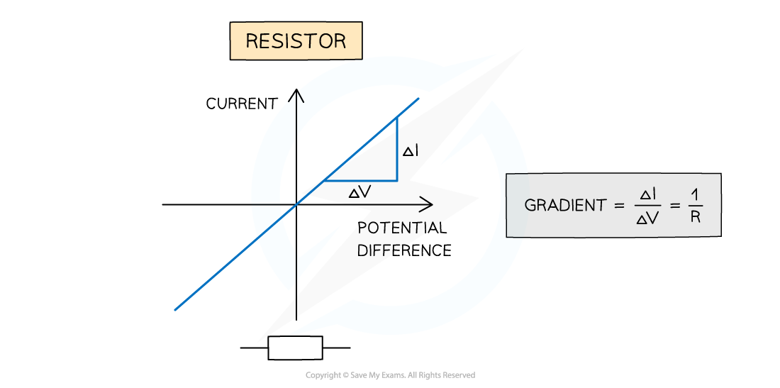
1. Metallic Conductor (Fixed Resistor) at Constant Temp
- Ohm’s Law: Current is directly proportional to p.d., provided temperature remains constant.
- Straight line through the origin.
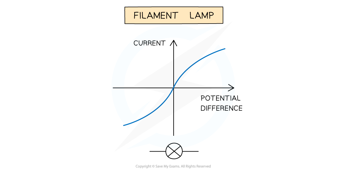
2. Filament Lamp (Non-Ohmic)
- Explanation (Paper 2 staple): As current increases, temperature increases. The metal lattice ions vibrate with greater amplitude. This causes a higher rate of collision with free electrons, impeding their flow. Hence, resistance increases.
- Graph curves inward (gradient decreases if is on the y-axis).
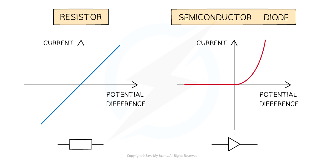
3. Semiconductor Diode
- Forward bias: Conducts easily past a certain threshold (approx 0.6V).
- Reverse bias: Virtually zero current (infinite resistance).
5. D.C. Circuits & Kirchhoff’s Laws
Circuit Symbols You Must Know
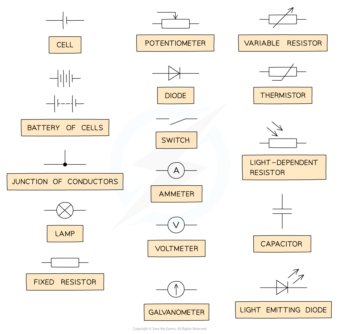
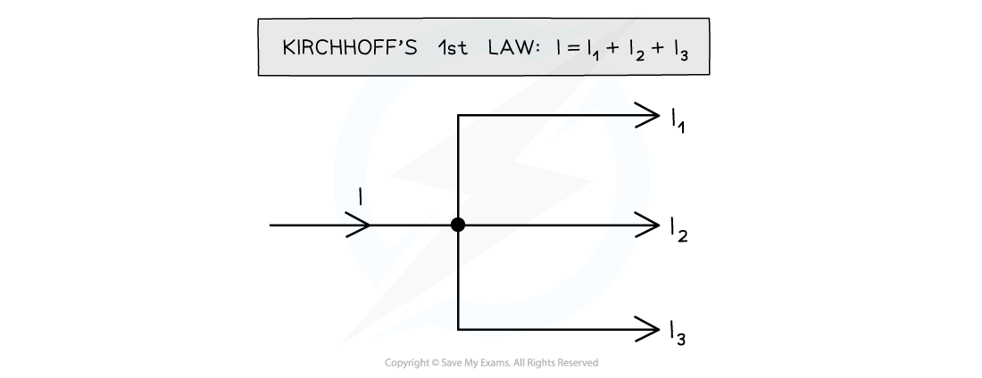
Kirchhoff’s First Law (K1L)
Law: The sum of currents entering a junction is exactly equal to the sum of currents leaving the junction. (). Fundamental Principle: Conservation of Charge.
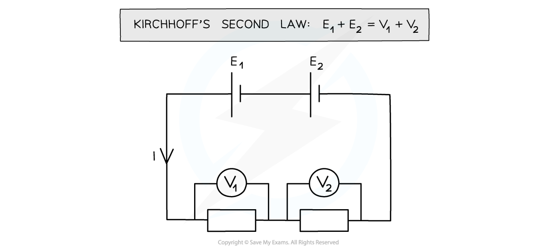
Kirchhoff’s Second Law (K2L)
Law: In any closed loop network, the algebraic sum of the e.m.f.s is equal to the algebraic sum of the potential differences. (). Fundamental Principle: Conservation of Energy.
Deriving Resistor Formulas (Frequent P2 Proofs)
Deriving Series Resistance (using K2L)
- Consider two resistors and in series with a supply .
- By K2L: Total p.d. .
- Current is the same everywhere. Since :
- Divide by :
Deriving Parallel Resistance (using K1L)
- Consider two resistors and in parallel.
- By K1L: Total current .
- Voltage is the same across both branches. Since :
- Divide by :
6. Potential Dividers & Potentiometers
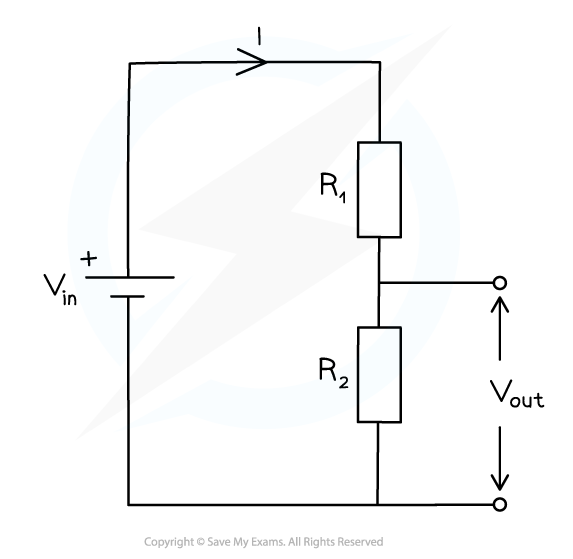
Potential Dividers
A circuit used to produce an output voltage as a fraction of its input voltage. Rule of thumb: The ratio of the voltages is equal to the ratio of the resistances (). The larger resistor takes the larger share of the p.d.
The Potentiometer (Null Method)
Used for highly accurate comparisons of e.m.f.s because at the “null point”, zero current is drawn from the test cell, meaning no “lost volts” due to its internal resistance.
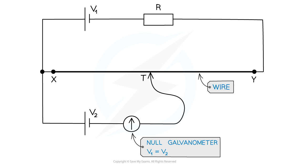
- The jockey/sliding contact is moved along the wire until the galvanometer reads zero (the “null” point).
- At this point, the p.d. across the length of the wire exactly balances the e.m.f. of the test cell: .
- Therefore, comparing two cells: .
7. Essential Past Paper MCQs (Test Your Knowledge)
Click the links to view the exact exam graphics.
Q1. Resistance of a stretched wire. (A classic ratio trap).
Solution Concept: If volume is unchanged, stretching a wire so diameter decreases to means Area decreases by . To maintain volume, Length must increase by . Since , increases by . Answer: D
Q2. Internal resistance graphical interpretation.
Solution Concept: Graph B shows a straight line with a negative gradient. . decreases linearly as increases. Answer: B
Q3. Kirchhoff’s Laws complex circuit.
Solution Concept: A bridge circuit. If the voltmeter reads zero, the potential at the left junction equals the potential at the right junction. This means the ratio of top/bottom resistors on the left equals the ratio of top/bottom on the right. . Answer: C
Q4. Ammeters & Voltmeters with internal resistance.
Solution Concept: Adding a parallel external resistor decreases total circuit resistance. Current drawn from the cell increases. Because of the cell’s internal resistance, more current means more “lost volts” (). Thus, terminal p.d. (voltmeter reading) decreases. Ammeter reading (total current) increases. Answer: C
Q5. Potentiometer logic (Null point movement).
Solution Concept: What is not a requirement? The internal resistance of cell X does not need to be known, because at the null point, zero current flows through X, hence , meaning the balance length measures the true e.m.f directly. Answer: B